This blog began in late 2006 with the planning and preparation for a circumnavigation of the world in my 39-foot sail boat Pachuca. It then covered a successful 5-year circumnavigation that ended in April 2013. The blog now covers life with Pachuca back home in Australia.

Pachuca

Pachuca
Pachuca in Port Angeles, WA USA

Saturday, November 24, 2018

Bad Hair Day

Bruce and I are now working off a task list of 33 items, which has been helpful in our scheduling preparatory work.

More work was done on bow roller modification.  Angle plates were welded at the bottom to facilitate the feeding of the chain when weighing anchor.  Lock down pins were fabricated and the fitting of the pins will be completed next week. 
Two of four pin holes have been drilled

No more of anchor chain jumping off roller
The first photo shows the plates that have been welded to the system to keep the chain on the roller and locked down by a pin.

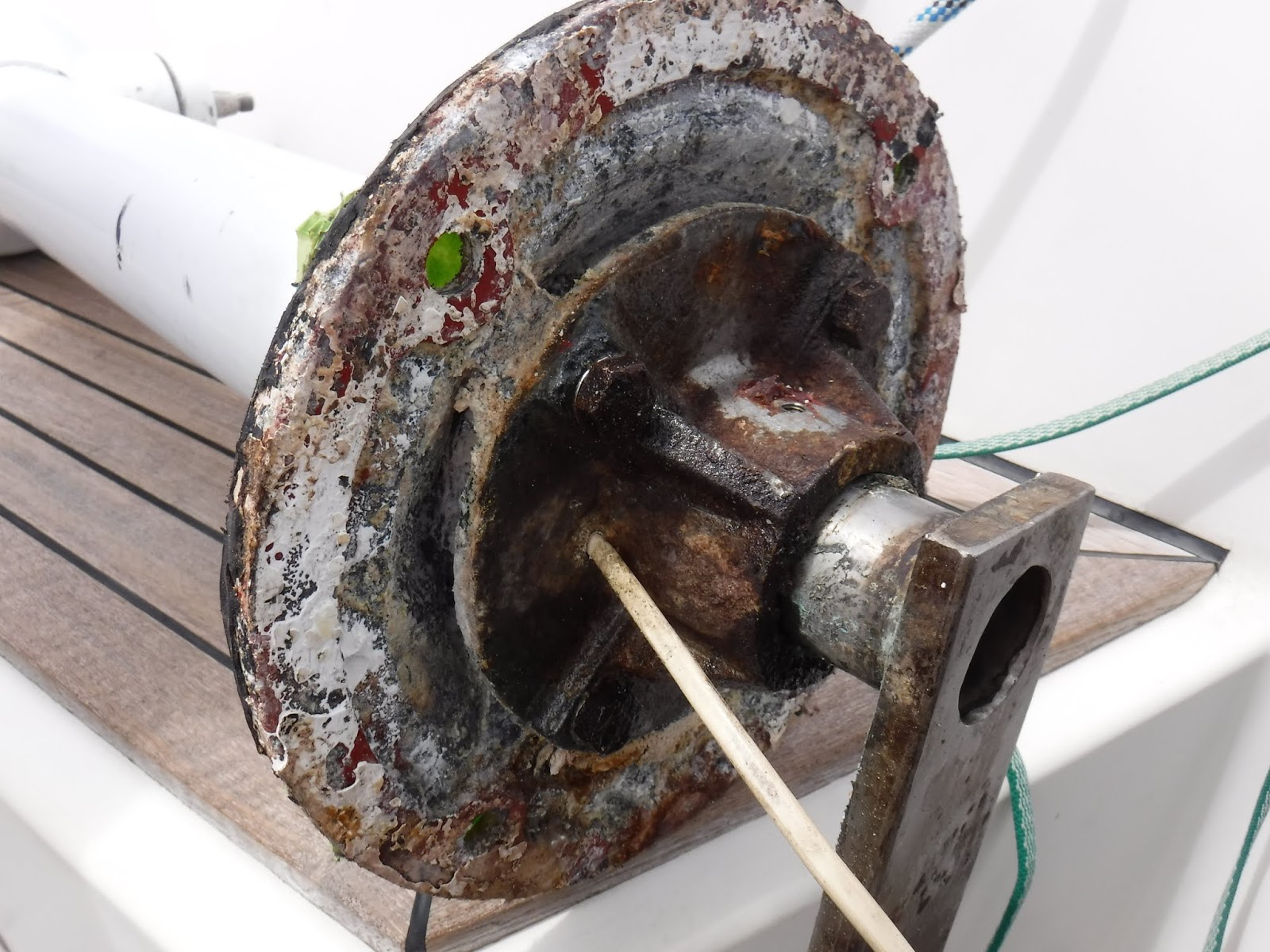
The shaft seal was reinstalled.  The company was able to reface the seal so I was not forced to purchase a new one.  On Friday Bruce re fiberglassed the end of the stern tube and on Monday the seal job will be completed by clamping on the bellows (ie rubber boot).  The mechanic will also re align the propeller shaft which for some reason is out of position.

Contact was made with a gas fitter who will replace the boat's LPG gas lines probably in January.

Now that the transom fittings have been bolted on Bruce has arranged for the boat's stern lettering to be put on in the coming week. 

Bruce and I did a lot of painting during the week.  I spent a difficult 3 hours laying down a coat of enamel paint in the lazarette, which I liken to painting the inside of a coffin with the lid down.  After the cramped work I emerged with my hair covered in lumps of enamel paint, some large, and some small and difficult to see.  I spent the rest of the day looking like Albert Einstein on a bad day and resumed the painting the next day armed with a pair of underpants to protect my hair.  I didn't relish the prospect of being seen wearing a pair of underpants on my head and was fortunately saved by the bag of rags that we had purchased earlier in the week.  One of the rags was large enough to act as a suitable head scarf.

The situation appeared to be so hopeless that I considered shaving my hair.  Fortunately a Google search came up with olive oil as the solution.  On Friday night I cut off about 10 lumps of paint with scissors while watching TV then on Saturday morning I saturated my hair with olive oil to the point where for the next 4 hours I had to have a towel around my neck to manage the oil that was working its way down all around my head.  During these four hours worked at the garage as usual, then when I was ready for a shower I soaked a bit more olive oil into my hair and got to work with a comb. Sometimes I could slide the lumps down with the comb and sometimes I would have to work the lump between my thumb and index finger until it seemed to fall apart.  Twenty minutes later I could pass my comb and hair brush through my hair with no snags and the crisis was over.

Mark the mechanic spent several hours doing maintenance on the engine. The coolant hoses have been replaced with proper ones, the coolant has been replaced,  and the heater has been fitted.  The gear box oil was at the correct level and looked good.  He will return next week to finish his work after Bruce's fiberglass work has set.
Adjustable LED light at top right


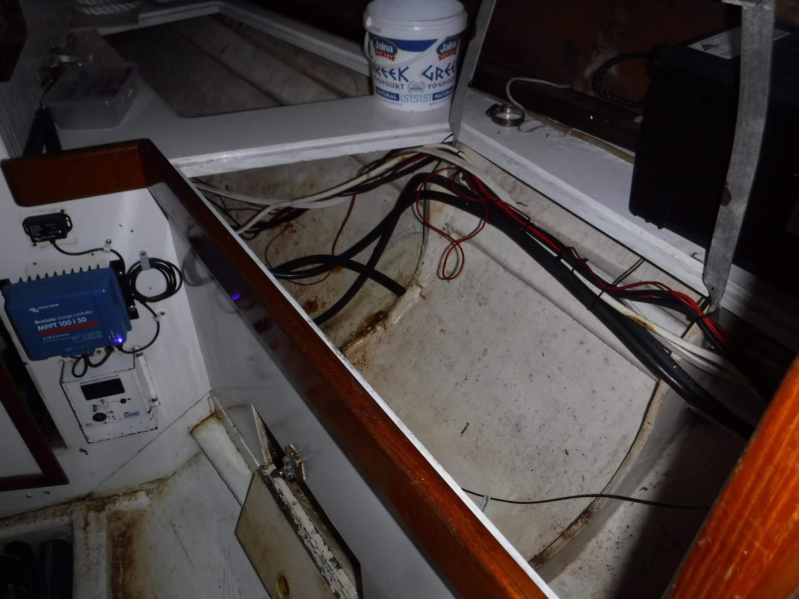
I am enclosing a photo of the steerage area with its floor board at LED light at the upper right.

Saturday, November 17, 2018

Binnacle Work Completed


The Cobra steering pedestal came back from the spray painter looking as good as new. 


New Scanstrut instrument pod

Rear View


We then assembled the binnacle on Thursday morning and concluded that the legs of the new stainless steel frame were too short because the instrument pod prevented the full opening of the compass cover and obstructed access to the drinks holder. Greg and I removed the frame without disturbing the steering pedestal or teak wood work then Bruce and I returned the frame that morning with a request that 100 mm be added to the vertical tubes and the slot for the wiring be lengthened by 20 mm.  By noon the next day we had the revised frame on board and Bruce had no trouble sliding the feet through the teak holder.  Greg arrived after lunch and spent the afternoon mounting the instrumentation.

The binnacle work had cost an obscene amount of money and effort but the result was most satisfactory.  We had solved the problem of mounting the Navman GPS onto the instrument pod by having Zelko fabricate and ingenious wooden support that would be screwed onto the surface of the pod.  The photo shows the autopilot panel on the left, the Navman GPS in the centre,  and the anchor windlass switch at the right.  (It was the problem of siting the new windlass switch that had led to the re design of the binnacle in the first place.)  The instruments are now all fully protected from the weather and the cabling is invisible, passing from the inside of the pod pod down the legs of the frame.

During the week Greg also installed a bright adjustable LED light in the steerage section beneath the cockpit, with the switch at the navigation station instrument panel.  What luxury!  A nice piece of flooring too keep me out of the bilge and a bright light to see what I am doing is a far cry from the section being a no-go area protected by a wall of batteries.

My attempt to connect the boat to shore power failed with a light on the new panel indicating incorrect polarity.   Greg took the cable home and swapped the non-standard connector that I had been forced to use with my old boat wiring with a standard (and legal!) one.  And, shame on me, Greg confirmed that I had wired the plug incorrectly with polarity reversed.

Bruce and I re mounted the boat's stainless steel nose plate.  It was a perilous job that could have ended in disaster with the slightest mistake but we managed it with no dramas.  Bruce's wife "Dolphie" had done a marvelous job of treating the metal with Ranex  rust converter then polishing it to a high luster.  It was the original nose plate, which showed the scars of previous battles with anchors, but to me it added character to the piece.
Applying Sikaflex to the bow plate

Plate in position

One day Bruce noticed some deterioration in the rubber boot and clamps around the PYI dripless shaft seal that had installed in Mexico in July 2010. A mechanic was called and removed the unit and noted some pitting on the metal face.  He took shaft seal away either refacing or replacement.  The rubber boot and clamps will be replaced, and Bruce will do some repair on the fiberglass at the end of the stern tube. 

We then had to remove the base upon which the engine covers slides in order that he may sleeve  two holes in the bilge barrier at the  front of the engine compartment.  That led to another day of distraction typical of this project.  We cleaned the oily area below the engine so well that I had to finish the job of removing dry specs of material using a vacuum cleaner.  We then found the beginnings of wood rot in parts of the engine cover assembly so we cleaned, sanded, then treated the wood with several coats of "Awlgrip".  In lifting the base one of the layers acting as a slide for the cover parted and we saw that it had been held together with tiny nails and a layer of Liquid Nails, something totally unsuited for a marine environment but was probably the standard when the boat had been built in 1983.  We put the base back into place, used 2-part "Megapoxy" to re glue the slide, then put the engine cover  back into position to ensure that aligned the track correctly and to apply force to the glued surfaces. 

We had a look at the engine while it was exposed and noted that once again the rack holding the oil filter had become loose with the top bolt loose and the bottom bolt missing altogether.  After some discussion I agreed to bring in an experienced Volvo mechanic that Bruce knew.  The next day the mechanic visited and we had a very productive discussion on the engine and how to manage it.  I have commissioned him to service the engine, which will exclude an oil change which he deemed unnecessary since fewer than 10 hours have been put on the engine since I changed the oil and filter less than a year ago, and the oil looked brand new.  I will also engage him to align the propeller shaft after the boat is back in the water.  One thing that I liked about the man is that he had no hesitation in explaining anything I asked, such as how to change the engine coolant.
Accessible Engine

550 hours of running since installed in Mexico in Jan 2011


Both the mechanics attending to the shaft seal and the engine both marveled at the accessibility of the boat's engine and propeller shaft.


Sunday, November 11, 2018

November Report 2

Pachuca's steering station has two components: the steering pedestal to which is attached the wooden binnacle which supports the compass. 

The Cobra pedestal steering is an all-gear system that is considered to be more reliable than chain or wire systems.  During final preparations for the circumnavigation in 2008 my friend Reg Kelly suggested that we remove it from the boat and have it checked out, and what wise advice that turned out to be.  We managed to remove it and deliver it to a local engineer who took it apart and found it to have a frozen bearing and totally dry of lubrication.  When  I picked it up a grease nipple was pointed out to me but after  the installation of new batteries in New Zealand I very rarely got access to the below-cockpit area for greasing the bearing.
After pedestal removed

Base of pedestal looking very sad

Two weeks ago we removed the unit and found it to appear to be in  bad shape with corrosion starting to eat into the aluminium base.  The bearing  was found to be in bad shape although not corroded, and it appeared that ordinary rather than marine grease had been applied in 2008.  After picking up the refurbished unit we sent it  out for re painting.  The spray painter had done a beautiful job and the unit presented as new. 

By then we had decided have the stainless steel binnacle rebuilt, to be higher and have a bend at the top for better presentation of the instruments.  I agreed mount a Scanstrut instrument pod which would look smart and protect the instruments from the elements.  The pod would also enable us to pass the instrument wiring down the legs of the binnacle rather than down the side as before. We then had difficulty in mounting the stand-alone Garmin 152H GPS which had not been designed for this kind of mounting but we came up with a solution utilizing the woodworking skills of Zelko.

So the instrument pod will accommodate the Garmin GPS in the centre, the Raymarine autopilot head at the left, and the anchor up-down switch at the right.

And last week Bruce and I managed to reinstall the boat's stainless steel bow plate.  The job took a lot of time and patience but fortunately there were no catastrophes.

Saturday, November 10, 2018

November Report 1

Five weeks have passed since my last blog entry.  In this entry I will cover the electrical work of the last few weeks.

Greg Hansen has almost completed what has turned out to be an almost total wiring of the boat which included the following:

1. Re-design of the anchor windlass power system
I had earlier accepted Greg's advice to alter the anchor windlass setup from from supplying electrical power from small battery at the bow that is trickle charged from the house bank to supplying it directly from the engine starter battery via heavy electrical cabling. 

There would be several advantages from the change: (1) Power would now be supplied from a hefty starter battery rather than a smaller AGM battery more suited for supplying steady power rather than starting engines, (2) The cost of the cabling would in the long run pay dividends because there would no longer be the need to replace windlass batteries, (3) Because the windlass would always be worked with the engine running there would be no practical limit on the frequency of anchor lifts whereas the old system had limitations since it relied on a slower trickle charge to replenish the windlass battery, (4) There would be less weight at the bow of the boat, a big benefit to Pachuca with her long and slender bow.
Rewired Windlass


It broke my heart to dismantle the trickle system because it represented a personal triumph of design and implementation.  My brother Arnold, an electrical engineer, supplied the design then Stephen used an amazing on-line simulator to see the behaviour of the circuit using various resistors, diodes, and the relay.  Stephen also provided a large heat sink which nicely took care of heat issues.  But we all agreed that the sacrifice of the good work was justified.

After confirming that the Orca VE 2000 windlass could reverse to drop as well as raise the anchor Greg installed the required wiring which included a heavy breaker at the navigation station.
Windlass Breaker

In future I will be able to raise and lower the anchor from the steering station, yielding great improvements in efficiency and safety.  But that led to the problem of finding space for mounting the new switch at the steering station, which led to a rebuild of the binnacle documented later.

2. Re-wired all of the battery cabling

Two of the house batteries and the starter battery had been re positioned to the starboard quarter berth locker which necessitated a lot of cabling work.  While he was at it Greg replaced the cabling between the two house bank batteries in the cabin.  During this work Greg suggested that we split the four house bank batteries into two separate banks in order to minimize the risk of one bad battery bringing down the entire house bank.  The cabling work included running special wires to the BEP voltage and amperage monitor, which I modified to display voltages for "HOUSE 1", "HOUSE 2", and "STARTER".

3. Replaced all of the internal 12v lighting  

All of the internal lighting is now LED.  Dome lights were installed in the aft bunk area, clothes locker, head, and navigation station.  For the first time I am able to use a red light at the desk when navigating at night.  Large LED lights were installed in the cabin and galley, and new high quality brass lights were installed over the cabin bunks and forward V section bunk.

4. New Switches 

A new switch allows me to direct power from the solar panels and wind charger to either house bank, and another one which allows me to use power from either house bank.  (House Bank 1 is the two batteries aft rated at 480 a/h and House Bank 2 is the two batteries in the cabin, rated at 540 a/h.) Note that the starter battery is charged solely from the engine alternator, and when it reaches full charge a voltage sensitive relay directs the alternator charge to the house bank.
Switch to direct solar and wind power

Switch to select which house bank to use


5. New lighting

Wiring has been set up for new lights at the cockpit and in the space below the cockpit and Greg expects to receive and install the new lights in the coming week.

6. Upgraded the 240V wiring to current standards

 Greg was legally and ethically obliged to upgrade the 240V AC system to current standards and I certainly did not object to that.  He put the heavy cabling in conduit, installed an RCD, and neatened the entire setup.

6. Installed an electrolysis blocker

Electrolysis Blocker
Greg installed an electrolysis blocker which will allow me to connect the boat to shore AC power with no fear of electrolysis due to faulty wiring of the shore power source.


7. Tidied Electrical Panel

Greg did a marvelous job of removing redundant wiring then tidying up the main electrical panel.  He also replaced switches with breakers in a new extension panel that I had installed on the door. I sacrificed the ancient (but working) Lowrance GPS in order to accommodate the panel for the 240V A/C breakers.

I finally have for the first time a very good understanding of the boat's wiring and plan to document it at first opportunity.
New switch panel lower left, A/C breakers at right

Wiring now tidy and and labeled

Thursday, October 4, 2018

Another Month of Progress

I was away for most of the month of September on a 3-week trip to visit family in the USA.  I departed knowing that I was leaving Pachuca in good hands and that Bruce would maintain his usual brisk pace of progress.

The first thing that I noticed on my return was the splendid look of Pachuca's hull now that Bruce had laid 3 of 5 coats of 2-part epoxy primer below the waterline.  Pachuca's sleek lines are striking and I received several compliments from admirers. 
Hull with 3 of 5 layers of  2-part epoxy  primer

Several other less grand but very important tasks had been completed. 

I had managed to circumvent the planet with plastic thru-hull fittings and no shut of valves at the stern and Bruce corrected this.  These outlets were above the waterline in calm water but would have presented a danger in rough seas.

The new fuel gauge had been fitted above the companionway, so that for the first time I would not have to guess how much fuel I had on board.
New Fuel Gauge

The two "Seabird" vents on the cockpit coaming that had caused me so much grief because they could not be blocked off from taking in water during heavy seas had been replaced with vents that could be rotated in any direction and capped off in heavy seas.

The new larger solar powered vent had been fitted above the head.  A larger hole had been cut through the deck and Zelko had fabricated from teak a level base for the vent.

The old-style Whale Gusher manual bilge pump on the starboard side of the cockpit had never worked.  Its role was to pump water out of a dead spot in the bilge below the cockpit.   Consequently that part of the bilge was always full or nearly full of water.  At some difficulty Bruce and Zelko fitted a new all-plastic Whale Gusher  pump to match the one at the rear of the cockpit.  So Pachuca now has two manual and one electric bilge pumps.
View to Foredeck

Solar powered vent

Bruce took delivery of the two new water tanks and new diesel fuel tank. 

The rebuilt rudder arrived at about the time of my return.  Rebuilding the rudder cost approximately $2,900, and this does not include the cost of the hours of labour in dropping and reinstalling the rudder.

I resumed my work of tidying up the electrical breaker panel, steadily removing redundant wiring. One afternoon Bruce gave me a had in pulling out a bundle of redundant wiring running from the lazarette to the main electrical panel.  The wiring was from the SABB diesel engine that I had replaced in Mexico.

One afternoon's worth of redundant wiring
We also spent the better part of 2 days fitting a relatively heavy copper strap between the HF tuner and the Dynaplate strapped to the hull.  This strap was heavy enough to last for many years but was extremely difficult to work into position.

Bruce and I discussed the installation of a light prism in the head and an order has been placed.  These prisms are very effective in gathering external light and directing it into the space below deck.
Zelko fitting batteries

Batteries strapped into position

The rudder was installed on Tuesday.   It took more than an hour of effort to jack the rudder stock into position.  New bushes were  used, which has eliminated a bit of play at the lower end of the rudder.  The packing also new, as would be expected.  I am looking forward to sailing the boat with the rudder contributing buoyancy rather than dragging the stern of the boat down because it is full of water.
New thru-hull fitting and valve.  Note backing plate.


At left is connection of earth strap to HF tuner

This morning Zelko showed up and set up the new bases for the stern batteries that he had fabricated.  One by one the heavy batteries were lifted into position then strapped down with the specially fabricated aluminium frames. Everything had worked out as planned and the result was pleasing in every way: neat, professional, and strong, and.  We figure that those batteries will now remain in place during a rollover. 


Then we installed the new diesel tank that Bruce had been carrying around in his van for about 2 weeks.  Once again everything has gone as planned and the new tank fit nice and snug on strips of rubber that Bruce had glued on the supports.  Zelko will strap the tank down after the tank has been plumbed into the boat's fuel system.  The tank is constructed of 3mm marine grade aluminium.

Greg Hansen the semi retired boat electrical man with whom I've been dealing with since the1980's visited late yesterday and we had a very productive session. 

He will start by cabling the batteries in their new location. 
Then he will also wire up the anchor windlass so that it will have a switch above the steering wheel for both raising and lowering the anchor.  The foot switch at the bow for raising the anchor will remain.  There will also be a switch at the cockpit for deactivating the entire circuit.  In order to accommodate the new windlass switch we will have the welder extend the stainless steel tube frame at the binnacle by 130mm.  While we are at it we will have slots cut into the vertical tubes of the frame so that the binnacle instrument (i.e. compass, autopilot head, GPS, windlass switch) can  pass into the interior of the boat without being seen and with much better protection than having the wires strapped to the legs.  For the first time I will be able to raise and lower the anchor while at the steering station rather than the bow, a great help when sailing solo.  Previously I had to lower the anchor manually at the bow.

Greg will also bring the 240V electrical cabling up to current standard: the cabling will be in conduit, an RCD will be installed at the switch panel, and the switch plywood panel will be replaced with non-combustible material.

Greg will also lead the way in wiring the starboard side of the boat, using the latest techniques for bundling the wiring.

This electrical work represents more mission creep but it represents a major step in making the boat safer and easier to handle.

I finished off the day by discussing with Bruce my selection of new interior lights for the boat.  After some helpful suggestions by Bruce we completed the order list which is going to be a big one: 4 reading lights for the forward and cabin bunks, two dome  lights for the  aft bunks, a dome light for the head, and large  lights for the galley and cabin.  All lights will be LED's
Strap bolted to the Dynaplate

Strap run  to lazarette
New coaming vent (sealed off) and Whale Gusher pump below


Rebuilt rudder in position
Top of diesel tank with inspection plate and fuel sensor at right

Drain will be fitted at the bottom of the tank.


New diesel tank in position

.


Saturday, September 1, 2018

Progress Report

My last blog is dated 26 July, over one month ago. I was away for about 16 days on a prearranged visit to the countryside.  The loss of time with the boat was balanced out by my lungs clearing up on the third day in the semi desert environment, after weeks of incessant coughing with bronchitis.  During my absence Bruce carried on and made splendid progress.

After being given an extension we were able to move the boat out of the work shed onto a hard stand on 6 August.  The working environment was radically different given that we were now fully exposed to the weather, but nevertheless I much preferred working in the open, in full view of the marina and Cockburn Sound.
On  the Hard Stand


The following is a summary of the situation:

- The rudder has been practically rebuilt.  It was split in half, cleaned out, filled with new foam, and re-fiberglassed. Special measures were taken to prevent leakage through the joins to the rudder shaft.  I can now look forward to sailing the boat with the rudder providing buoyancy at the stern rather then weighing it down with water.

- The propeller is back on with a straightened propeller shaft and new cutlass bearing, courtesy of Precision Marine.

- The base plate supporting the mast compression post has been fabricated of 10mm marine grade aluminium, has been powder coated and is ready for fitting. 
Bruce with New Base Plate

- Bruce has almost completed the osmosis treatment, and only a few repairs need to be faired.  I ran my hand over the repairs and was amazed at the smoothness of the result. 

- In working on the main hatch to smooth its slide action we discussed the problem of the fiberglass  cover under which the hatch slides, known to some as the "garage" and others as the "turtle".  The problem was that it was extremely difficult to avoid standing on the garage when attending to the end of the boom, particularly in rough seas.
New Teak Hatch Cover Protector
  This posed a great risk of cracking the fiberglass.

In consultation with Zelko it was decided that he would fabricate a teak cover over the garage. This would allow one or two crew to stand on the platform to work on the boom and would provide a nice vision of teak that matches that at the bow.  A very special plank of top quality teak was ordered, with the photos sent to Zelco to confirm that the grain ran as he required.  As I picked up the plank to deliver to Zelko's house I asked about the quality of the teak as I handed over $535.  The man proudly assured me that it was top grade teak out of Burma.  Zelko then milled the wood into boards and fabricated the cover.  The result was outstanding, and up to the standards of Zelko's very experienced craftsmanship.

- The new stainless steel water tanks have been completed and are being stored in a container not far from the boat.

- Bruce, Zelko, and I had a discussion about the extremely very unsatisfactory access into the lazarette under the rear seat.  The unsealed doors allowed water to curl into the lazarette from the seat above and also enter from below whenever the cockpit was flooded with more that 75 mm of water.  The decision was to replace the doors with a curved plate that would fit over the opening and held in by flush fasteners. 
Bruce holding up new lazarette access cover


The job was issued to Rob  and I expected a simple piece of curved metal.  Instead I got a work of art worthy of a million dollar boat.  In fact Rob builds hatches for all sorts of boats, including patrol boats of the Australian navy.   The cover has been powder coated to match the colour of the cockpit but I have yet to see the result. Bruce and Zelko will fit the cover during my absence.

I am very much looking forward to the prospect of sailing in a rough sea without seeing water sloshing side to side on the lazarette floor before it works its way down into the bilge.  The will represent another correction to a building/design problem.

- The tiny 6 mm diameter rear cockpit drain has been replace with much larger  13 mm diameter one.  This required a new hose and larger through-hull  fitting and the work had been magically completed when I returned from the trip.

- Another magical completion was the replacement of the old-style aluminium Whale Gusher pump on the starboard side of the cockpit. This pump probably dated from Pachuca's construction and had never worked.  It was designed to drain a void below the cockpit where water was trapped and could not flow into the rest of the bilge unless the void filled up and overflowed.  Now I have two modern and working Whale Gusher pumps at the cockpit to complement the electric bilge pump in the cabin.

- The big problem that emerged during my absence was the state of the boat's fuel system.  I had discussed with Bruce my concern that the fuel tanks were completely sealed other than the drains at the bottom for removing water in the fuel.  The tanks each held 70 litres of diesel and I always kept them full in order to avoid the introduction of water through condensation.  However, I use no more than 40 liters of fuel a year, meaning that the diesel must have been getting staler and staler as time passed.  I had placed my hope on the generous amounts of biocide fuel conditioner that I use and the fact that the fuel vacuum gauge never indicated a clogged fuel filter.
Unhealthy Colour of the Diesel Fuel

Flakes at the bottom of this pour

Discarded pump, fuel lines,, tanks, etc

Rust on fuel tanks
Bruce investigated and found everything to be wrong.  The fuel smelled like urine, complete with yellow colour, and appeared to be more like a mixture of diesel and turpentine.  There was water in the fuel as well as flakes of material and black gooey lumps, which I think represent dead fungus.  The Racor fuel filter was filthy.  The filler hoses were lined with fungal slime and the breather hoses were not fuel rated and stiff as a board.  Bruce cleaned out the Racor fuel filter unit at considerable effort and replaced the fuel filter, which I am ashamed to say was the original one installed with the engine in Mexico in about 2012.  I had relied on the vacuum gauge whose needle never moved off the peg, and Precision Marine advised that in future I should pay no attention to the vacuum gauge as a guide to the state of the fuel filter.

Because the fuel tanks were exhibiting rust and in any event could not be cleaned because there was no access to the interior it was decided to replace them.

By then Bruce had come up with another idea. Access to the the area beneath the cockpit had been impossible due to a wall of batteries acting as a barrier.  This battery layout had been set up in Opua NZ while Brenda, Arnold, and I had been touring the North Island and I considered it to be imaginative and satisfactory.  But the area contains important items of equipment such as the cockpit drain shutoff valves, autopilot, and manual steering.  Sailing the boat without fast access to this area represents a risk.

Bruce suggested placing the batteries in the aft section of the quarter berth lockers.   This would reduce my storage space which I considered a worthwhile tradeoff for gaining access to the below cockpit area.  We started measuring and ran into space difficulties in fitting the batteries.  I then  proposed idea to Bruce: fabricate only one tank to be put in the narrower port port locker space and place all three batteries in the wider starboard locker space.  Bruce took to the idea immediately and careful measurements that included the use of cardboard cutouts confirmed that the plan was feasible.

My measurements of the proposed tank suggested a rough capacity of 220 litres, a significant improvement over the previous 140 litre capacity from the smaller and round tanks.  The gain in capacity was due to the straight sides of the tank and much longer length.  That night I arrived at the following weight distribution calculations:

Century CR12-270 DA ... 74 kg
Century N20 MF ............. 32.1 kg
Fullriver DC210-12 .......... 60.5 kg
                                          -----------
Total                                   166.6. kg on the starboard side

Weight of 220 litres of diesel:  184 kg on the port side.

After Ron's preliminary measurements it appears that we can expect 200 litres of diesel weighing 166 kg.  You cannot get better balance than that!

Batteries blocked access to under-cockpit space
On Thursday Ron,  the man who had designed and fabricated the masterpiece for the lazarette visited the boat.  He works only in aluminium and suggested 3mm aluminium plate..  We were fortunate in that he had just completed work on a big fishing trawler and was in a quiet time.  Later Bruce suggested to me 4mm plate, which I had expected in the first place but had not questioned the opinion of the fabricator.  At the end of our day as I was about to get into my car Bruce came up with the best idea of the week.  He asked if I would like a fuel gauge.  Wow, would I!  He told me that it would be relatively cheap and easy to install at the tank fabrication phase.  We will put the fuel gauge along side the wind and depth instruments above the companionway.

Site of new fuel tank
The next morning Bruce left a message for Rob specifying 4mm plate and a fuel gauge.

I am looking forward to for the first time know how much fuel is in my tank rather than keeping track of engine hours.


Blog Archive

Contributors

Statistics Click Me