This blog began in late 2006 with the planning and preparation for a circumnavigation of the world in my 39-foot sail boat Pachuca. It then covered a successful 5-year circumnavigation that ended in April 2013. The blog now covers life with Pachuca back home in Australia.

Pachuca

Pachuca
Pachuca in Port Angeles, WA USA

Sunday, December 11, 2016

Solar Panel Switch

The installation of Pachuca's two 60-watt solar panels in 2008 was straightforward and simple: pos and neg wires from the panels to the regulator, with two diodes in the path, the regulator clearly marked with two connectors for the solar power, two for the battery, and two for the ground.

I embellished the design by connecting the pos to an ammeter then to a switch with positions 1, 2, 1&2.  The ammeter has proven to be invaluable because I can see at a glance how much power the panels are delivering.  The idea of the switch was to give me control of the destination of the solar power current: starter bank or house bank.  The flaw in that system was that whenever I selected 1&2 the regulator would go into a fit of clacking, no doubt because I was joining the two banks through that switch. So I learned to direct the current to one bank or the other, but not both.

The switch fell apart while I was working in the area two weeks ago and the regulator went berserk, so I made a hasty disconnection.   The postmortem on the switch revealed that all four plastic channels into which the four screws holding the switch together were threaded had broken.  A visit to the boat shop revealed that a replacement would cost in the order of $80.  I concluded that impressive as the appearance of the switch may be, it is basically cheap plastic junk masquerading as quality.

I thought of doing without the switch because there really was no need for it. If I directed the solar power to the starter bank the Voltage Sensitive Relay (VSR) would ensure that current would be directed to the house bank when the starter bank was fully charged, and if worse came to worst I could always join the starter and house banks (as I've had to do twice to get the engine started).

Nevertheless I like the idea of manual control so I went to Bunnings looking for a suitable switch at a realistic price.  I had little trouble finding a 240V outdoors rated set of two slider switches at the princely price of $20.  The quality and durability of that set has it all over that junk switch at the boat shop.

It seemed like a simple job, but it took me most of yesterday to make the installation.  The problem was in the practicalities of implementing the simple design.  The wire had to be of the right size and grade (a trip to the boat shop) and all of the connectors had to be the correct size and type (oops, another trip to the chandlery), and there was a lot of cutting, crimping, and connecting to do.  And there was much concentration in removing and reattaching tiny very special screws blindly and with one hand in an area where if I dropped a screw it would be lost forever.
New Switches for Solar Power

But the result was good.  I got a scare when the regulator showed "boost" with the ammeter showing 0 amps, until I remembered that I had covered the solar panels with blankets (duh!).  I threw one of the switches and presto, the ammeter showed 8 amps pouring into the starter bank.

I will soon label the switches to indicate that the left one is for the starter bank the right for the house bank, and to switch banks by first making sure that both  bank are off (ie do not have both banks on simultaneously, even if for an instant).

A little awkward?  Yea, maybe.  ... But it's my boat.

The photo, top down: ammeter, Arrid solar regulator, new switches, and the wind charger regulator (hard wired to the starter bank).

Saturday, December 3, 2016

New Windlass Foot Switch

In preparation  for the reinstatement of the electric anchor windlass I installed a new deck foot switch. 


Hole Cut Through Deck

New Switch in Place
Switch on Bedding Compound and Finished
When I had the boat re teaked in Mexico I elected to leave out the foot switch pending the reinstatement.  Thus the first task after purchasing the new switch was to cut a hole of 63 mm diameter through the deck with no mistakes.

Windlass Repaired and Working

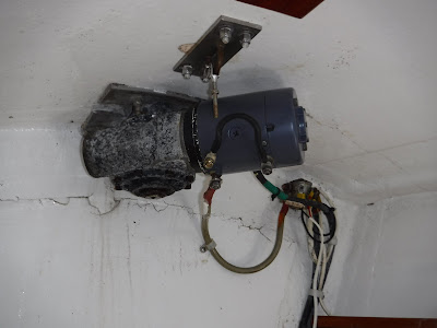
In preparation of the reinstatement of the electric anchor windlass I decided to clean all of the connections of the windlass, which were corroded to the point that they were beginning to resemble lumps of green.  I worked carefully and patiently, using the assistance of WD-40 in loosening each nut.  I would then use sandpaper to clean all of the contact surfaces until I saw bright metal.

Unfortunately I wasn't patient enough because I sheared off the last bolt.  I removed the motor housing and saw that because the bolt was soldered to various internal connections the repair job was beyond my competence.  Through a local chandlery I contacted someone who I will call MR X, who ran a mobile marine electrical business.
Windlass at installation in 2008 (Note jumper cable)


The project became an example of what happens when the tradesman will not listen to the customer and the customer is not assertive enough.
After repairing the broken connection bolt Mr X fitted the motor case upside down even though I insisted that was 180 degrees out.  He spun the case around several times and insisted that it would click into position only his way.  What saved the day was that the connection bolts were so close to the ceiling that he could not fit the nuts, forcing him to have a really close look and getting it right.
Mexico 2012 (Note black cable to top of windlass)

Then he insisted that the wiring sketch that I provided must be incorrect because there was no connection post at the top of the case.  The mention of "post" threw me off the scent and I relented because I could find no post at the top of the case and was puzzled because I NEVER make mistakes with basic sketches.  Mr X got the winch working after two short circuits resulting in major flashes and one half success where the winch was going, but backwards.  Oh, and he replaced the short jumper cable that had broken off at one of the connectors with a longer one that would reach the windlass case, never wondering how the original shorter cable could have spanned that distance.
My fundamental mistake was that I expected a marine electrician to know how to connect a windlass from experience.  This man acted as though he had never seen a windlass before. 

To avoid having to do some re-typing, here is a slightly edited version of the message that I sent to MR X:
Wiring by the Expert


Hello ,
You will recall that I had misgivings about the connection last Friday of the Orca VE2000 windlass on my boat Pachuca that you repaired.  Yes, I know that the windlass seemed to be working fine, but I was particularly concerned about the grounding cable from the motor to the gear housing, something that I knew was not as before.
I spent some time locating photos of the windlass to confirm that the diagram that I had sketched and presented to you was correct. 
Have a look the attached photos.
One photo shows the Orca at installation time in New Zealand in 2008.  The battery cables have not been connected, but you can clearly see the short jumper cable as sent from the factory.

Another photo shows the windlass in Mexico in 2012, which I took while painting the forward section of the boat.  You can  see the black battery negative cable passing to the top of the unit.
Wiring by the Owner

Also attached are photos of the cabling as you left it on Friday, to be compared with the photo as the cabling as I left it yesterday.
The mystery of the lack of post at the top of the motor case was simple to solve.  I felt along the top of the case and immediately felt a bolt hole. The bolt that you used to connect the black jumper cable to the windlass was in fact the bolt for connecting the black negative battery cable to the top of the motor case.
Why did the wiring work both ways?  I found the wiring diagram for the Orca VE2000 and working with a friend we concluded that the unit is capable of lowering as well as raising the anchor.  Mine is set up for raising only.  Because of the complex internal wiring it is possible to get the same result several connection paths.
Having said that, you'll understand why I prefer the connection as before.  It looks like the jumper cable connects F1 and F2 (F for "Field"), which are used for raising and lowering the anchor.  This was probably done because the windlass was shipped for "raise only" as the default.  The red positive battery cable is connected to "A" (for "Armature").  The black positive battery cable is connected to the top of the case.


Regards,
Robert


Reinstating the Anchor Windlass - Part 1

Pachuca has not a working electric anchor windlass since 6 Feb 2011 when Brenda and I were lucky to not lose the boat and swim for our lives in an electrical fire during the passage from Isla San Francisco and the fishing village of San Evaristo in the Sea or Cortez.  (see http://pachucaroundtheworld.blogspot.com.au/2011/02/fire-and-water.html)

I knew that basic cause of the electrical fire was the direct connection of the house bank of batteries to the windlass battery with two fairly light gauge wires and no fuse, diode, resistor, or any other protection measure in the circuit.  I vowed not to restore the windlass until I was confident that I was using a safe design.  The problem was how to somehow trickle charge the windlass battery from the House bank. In the subsequent six years I have raised anchor manually using a winch handle on top of the windlass.

Fortunately my brother Arnold is an electrical engineer, and he was able to send schematics of possible solutions.  However, it was not until face-to-face discussions with him during my recent visit to the USA that I felt confident enough of my understanding of the designs to actually do something.

The basic design is:


The design addresses the analysis that the fundamental problem is the amperage not during normal recharge, but whenever the anchor is being raised when the windlass battery is at low voltage, which passes the entire load of the windlass motor, an Orca VE2000 rated at 1500 watts, to the house bank.  Thus the key component is a relay which cuts off the connection between the two banks while the windlass is energized and the anchor is being raised and reestablishes it when the windlass is idle.

I started off by purchasing a new windlass battery.  I was first offered a lead-acid battery for about $300 but I'm done with lead-acid batteries on boats and insisted on an AGM or gel battery.  I purchased an Ultimate Xtreme” 110 a/h, 546 CCA AGM battery for $449.


At this point Stephen, Brenda's son, became interested and he provided invaluable help that complemented Arnold's ongoing assistance.

A fundamental question was the gauge of wire sufficient for connecting the House bank to the new windlass battery.  Arnold had calculated that the current along the wires would be well below 5 amps, so I settled on the thickest wire in the shop that would fit into a large crimp connector, which has an area of 4 mm sq giving a capacity of about 12 amps.

Then it was time to procure a relay, something that I knew nothing about.  Stephen pointed me to Jaycar where I purchased a 10-amp car relay.   I learned about the 5 pins on the relay from Youtube and most important, that I had to use pin 87A instead of 87 because I wanted the connection to be made by default and broken when the trigger activated the relay.

Stephen educated me on resistors where heat generation and dissipation was a big issue and we settled on a pair of .47 ohm resistors.

Then it was diode time and I purchased a 6 amp diode, the largest capacity available at Jaycar,

Stephen then salvaged a large heat sink from an amplifier that he was dismantling for part.  This went a long way to solving the heat dissipation problem and also provided a platform for the other components.
Heat Sink

Stephen also introduced me to a wonderful circuit simulator that allows him to define any circuit that he chooses them run it to see what happens.  We verified that the design would work and were able to explore the interaction between the strength of the resistors and current flow, particularly when the differential voltage is low.

At this point I have the system almost completed and ready for testing (gulp!).

15 amp in line fuse
 The heat sink "board" is tucked high at the end of the sail locker, protected from water and encroachment by sails and equipment stored in the space. The green electrical tape along the lower part of the board is to prevent short circuits.  Stephen thought that it was a good idea to put an in-line fuse at the beginning of the cable run.  It is a blade-type fuse inside of the small red plastic case along the wiring.

I have mounted the relay at the top right corner of the board.  When the relay is triggered the connection will be made and current will flow through the two resistors (white) and the diode (small, black and gray).  The idea of the diode is to prevent the charging of the main house bank by the windlass battery.
Heat Sink and Components

I wanted to use a 15-am breaker at the main switch panel, but the panel is full to capacity I deemed freeing up a breaker to be too difficult and dangerous.  (The rebuilding and extending the main panel is a project for the future.)

Instead I purchased a 15 amp breaker from Jaycar and mounted it by drilling a small hole in the electrical panel.  This style of breaker cannot be manually set and reset, but fortunately there was a free switch (Test Bat 1, Test Bat 2) that works so that I will have the capability of manually shutting down the entire circuit.

In parallel with this was the repair and installation of the windlass itself, which will be covered in another blog entry.


Tuesday, May 17, 2016

Bubble Trubble

From memory,  it was La Paz Mexico that the boats Plastimo Olympic 135 compass developed a small bubble.  But it was during the heavy rolling below 50 S in my approach to the Horn that the bubble got bigger and bigger.  Fortunately the size of the bubble did not increase after my arrival in Fremantle,  but the matter had to be dealt with because the card was now very difficult to read.  Also, neither compass light was working.

One thing about boating is that it forces you to learn new things.

I removed the compass knowing nothing about it beyond how to change its lights.  I didn't know what fluid would be required, or how/where to inject it.

I got various suggestions about the fluid: glycol, baby oil, kerosene, and "compass oil", whatever that is.

At Yacht Grot Roger produced some clear fluid in a clean jar that he said was highly refined kerosene, with the assurance that it would mix well with the existing fluid in the compass, sparing me the trouble and expense of fully draining it.
Big Bubble in Compass


Rubber Membrane

Stephen arrived for an overnight visit on Sunday morning and soon we began our work.  I had dismantled the compass enough to identify the filling screw, which I exposed after cracking the epoxy seal on it.  On his advice I had also purchased plastic syringes at the chemist.

We worked for hours but try as we may we couldn't shrink the bubble beyond a certain point.  We stopped our effort with the thought of perhaps immersing  the entire compass in fluid to ensure that we could evacuate all of the air.

I was a bit despondent because even if we could shrink the bubble there was no guarantee that it would not return due to some leak somewhere.

In the afternoon Stephen helped me to join Ebay and link it to my Paypal account then we did a search for another compass.  Soon we identified a pitfall: There are at least 3 versions of Plastimo 135 compasses,  the "Offshore", "Horizon", and "Olympic",  different from each other and at different price points.  It took a while to confirm that I wanted the "Olympic", which was priced on Ebay at just over $620, a bit rich for my blood.  Later that night I found one Queensland priced at just under $400.

On Tuesday morning I  got back onto the web to find the Queensland company's contact information and stumbled on a compass at Whitfords Marine near Fremantle for $349.  I  phone up, they had one in stock, and they agreed to hold it for me.  Two hours later Stephen and I arrived, put the new compass and my old one side by side, and confirmed that they had identical specifications.  I purchased the compass and two spare globes.
Old and New Compasses

From our web searches we had concluded that "mineral oil" was the most likely compass fluid.  I needed more fluid because I had used all of the fluid that Roger had given me.  We stopped at Bunnings on the way home and found a liter of "paraffin oil" that seemed suitable.  It was clear, of light viscosity, and had  a neutral smell - certainly not of kerosene.

Yesterday morning I resumed work  on the old compass because I didn't want to simply throw it away.  I started off  by putting the compass in the freezer for 2.5 hours on the theory that the fluid would shrink, making the bubble bigger, allowing me to expel more air, then the remaining bubble shrinking as the fluid got warmer.  The flaw in this theory is that we discovered a rubber fluid-filled membrane at the base of the compass whose purpose was to allow for expansion and contraction as the temperature varied.  So how could the bubble size vary with fluid temperature given that the rubber membrane would do the compensating?

What finally did the trick, in my opinion, was that I discovered that the end of the syringe could seal the filling hole quite effectively with only a little pressure.  This enabled me to overfill the compass while I watched the rubber bladder expand, then allow the fluid to spit out when I released the syringe, bringing out bubbles of air with it.  After doing this a few times I reduced the bubble to the size of a match head, but try as I may I could not completely eradicate it.

Nevertheless the compass is now quite acceptable for use and had I not been able to source a new  replacement I would have reinstalled the old one, hoping that the bubble would not increase in size over time.
Spot the Bubble

My plan is to set up the old compass as an adornment in  my house which is already laced with nautical decorations.

I cannot complain about the compass problem.  It is with little doubt part of the Pachuca's inventory when she was launched in 1983.  The new compass has a 5 year warranty and will probably see me out, unless I live beyond 106.

Regarding the failed lights, I discovered that the wiring to the compass was delivering less than 3V.  I tracked the  problem back to the grounding in the electrical  panel.  The grounding had been set up before my time, to a white wire that was part of a bundle of white wires that would have been difficult to track.  I elected to earth the wire directly to the ground side of the switch panel and began to get over 13.5V at the binnacle.

Gas Detector Fixed

The gas detector failed ruing the recent overnight  passage to Bunbury.  Normally there would be an error light corresponding to the detector having the problem,  but this was a general alarm which I had never seen before. 
Controller Inside Cupboard

Paul and I bypassed the controller and supplied power directly to the solenoid switch in order to use the gas stove.

Sensor now at top left.  Old sensor at bottom right.

Sensor in Lazarette
I then managed to find a new replacement of the same make and model for an all-up price of $600, which seemed a bit steep but OK because  I would get  parts compatibility.

I installed new unit and got the same alarms signal, which indicated that the old controller was OK and the problem was in one of the sensors.  It turned out to be the sensor in the lazarette, between the gas cylinders.  I then re installed the original controller with a replacement sensor from the new unit that I had purchased.  That worked OK but then I made the wise decision of testing the sensors using a rag soaked in gasoline.  The brand new sensor in the lazarette worked OK but the one in the galley below the stove failed.  I then replaced it with the second sensor from the new unit.  I installed the new galley sensor in a position well above the sole because  the original position was too low and subject to soaking when the shallow bilge overflowed while the boat was rolling.

The $600 wasn't completely wasted because after using the new sensors I've now got in reserve a new controller and solenoid valve.   The spare solenoid is good because I once read a letter from a couple who were not able to cook for weeks because their gas solenoid valve had failed.

Cleaned and Protected Connections
After finished the gas detector work I cleaned the connections of the lightning protection cables at each side of the mast then sprayed them with Lanox.  The cables connect to bolts of the heavy lead keel.  There are also cables from the chain plate but they were clean.   I don't know if these measures ever protected the boat but I do know that I didn't suffer any lightning problems during the 5-year circumnavigation,

Battery Intalled

After returning with a 2-week bird survey expedition to the Great Western Woodlands I continued my effort to install the new starter battery.
Battery Job Finished

The photo above shows the end result.  The two gel batteries are back in the upper position, with posts and connectors clean.  Below is the single new starter battery, with wooden spacers on its left to fill in the void left from what previously a second starter battery.
Dead Starter Batteries

Terminals in Need of Cleaning

The battery setup goes back to Opua, New Zealand, in 2008.  We had departed from Fremantle in May with only three batteries, two sealed Delkor N120 800 CCA calcium sealed batteries, one each for the starter and house banks, and one deep cycle lead acid battery for the house.  This turned out to be woefully inadequate.  Night after night when crossing the Tasman Sea the gas detector would begin chirping at around midnight due to low voltage and at dawn the house bank would be down to as low as 10.5 V.


In NZ a consultant was brought in and the result was a house bank with 4 x Commander GDC232 230 a/h gel batteries and a starter bank with both of the Delkor batteries.  The mechanics were brilliant in their installation of the Gel batteries: two on a shelf above the starter batteries and one on each side of the cabin, below the seats.  This resulted  in excellent weight distribution, all below the waterline.

New Battery with Spacers at Left
The starter bank failed during the recent Bunbury Cruise so I removed them and had them tested by Battery World, which pronounced them well beyond dead.  (The worse battery held a CCA of less than 10.) The decision was to install one replacement starter battery, a Century N120 MF with 900 CCA and dimensions identical to the replaced Delkors.  It is a sealed battery frequently used for starting heavy industrial equipment.


I began the replacement project by making what turned out to be a big mistake:  I removed the Gel batteries from the upper shelf before extricating the ailing starter batteries below.


Gel Batteries to be Lifted

I began the installation with two wooden spacers on hand to take up these space of the second battery.  That went OK but as I expected, lifting the 65 kg gel batteries back into  position was beyond my capability, given that I had endured two weeks of back pain after removing the dead starter batteries.  The problem was made worse by the fact that correct lifting posture was impossible in the confined space.  I spent literally hours cleaning battery terminals and connectors while ruminating on what to do.  (Everything was so corroded that it's a wonder that I got any power at all.)

I finally got the bright idea of contacting Kim Jamieson,  the man who seems to do most of the pen rope work around the club.  Jim agreed to help and on the day I had a vast array of wooden blocks, planks, and even two car jacks to assist us in making the lifts without straining our backs.  Kim eventually did it his way, with a combination of good technique, various planks and blocks, and muscle grunt work.  (Thank you Kim!)

Then I stepped back and saw that I could have left the upper gel batteries and place and simply slid out the starter batteries below.  (DUH! You live and learn.)

Below the Cockpit
While the batteries were out I  took a photo of the below-cockpit space.

To the left is the  multi-layered copper strap connecting the Dynaplate outside of the hull to the HF radio tuner in the lazarette.

In black is the autopilot linear drive directly connected to the rudder post in the center of the photo. To the right in black is the mechanism that measures the angle of the rudder for the autopilot.


Saturday, March 26, 2016

2016 Bunbury Cruise

The following is the draft of an article that will be published in the FSC "Blue Water Bulletin" magazine, with the photos that will appear in the article.

-------


This year’s Bunbury Cruise was very successful, with all boats and crews returning safely after the enjoyable 3-week adventure.

The customary pre-cruise dinner was held at the FSC Galley on Fri 11 Dec followed by a discussion in the Stateroom of the coming cruise led by Robert Morales in his role as cruise coordinator.  At this meeting Ric Oswald of the Mandurah Offshore Fishing and Sailing Club gave valuable information to the group on the perennial issue of depth of water in the approaches to the MOFSC marina.

A second dinner followed by the skippers’ briefing was held on Fri 5 Feb.  By that time all skippers had received the Cruise Notes, which are now distributed via email.  The official start date of the cruise was Sat 13 Feb with the requirement that all boats be at Koombana Bay by Tue 16 Feb, giving skippers wide discretion in taking advantage of favourable winds. 

Only 7 boats and 16 crew were registered for this year’s cruise, a marked reduction from the previous year’s 13 boats.  They were:
                Alyssa Lee (FSC) with David & Joanne George
                Diva (FSC) with Ron & Marlene Viney
                Georgia (HYC) with Hugh & Robyn Nankivell
                Leola (SPYC) with Merv & Leola Holst
                Pachuca (FSC) with Brenda Newbey & Robert Morales
                Stealaway (FSC) with Frank & Lucinda Daly and Graham & Susan Suttle
                Volare (RFBYC) with Zac & Anne Armanesco

Five boats departed FSC on Sun 14 Feb with Georgia already in Busselton and Volare waiting at MOFSC.  Alyssa Lee, Diva, Leola, and Stealaway employed the proven strategy of sailing to Mandurah 30 miles to the south then making the 50 mile passage to Koombana Bay Bunbury when the winds were fair.  Pachuca as usual did it the hard way, departing at 0030 and making directly for Koombana Bay, an 85 mile passage that resulted in 20 hours of beating hard against a SE wind while attending to a seriously seasick novice crewman who appeared to be more dead than alive.

By Wed 17 Feb the entire fleet was a Koombana Bay enjoying relaxed living at anchor under the hospitality of the Koombana Bay Sailing Club. 

On Fri 19 Feb the group sailed the 28 miles to Busselton for two days on anchor at the Geographe Bay Yacht Club.  That evening they enjoyed a splendid meal at the GBYC galley and met for drinks at the club bar on Saturday.  Alyssa Lee was no longer with the group because she had returned to Fremantle from Koombana Bay as planned.

Quindalup

BBQ Breakfast

Morning Tea During Bus Trip

Pizza Dinner at Koombana Bay Sailing Club

Moored in front of Dunsborough Bay Yacht Club
Then the boats headed for Quindalup for 3 days on moorings at the Dunsborough Bay Yacht Club.  The DBYC was most hospitable, opening the bar especially for their visitors and arranging a special barbecue dinner where members and guests mingled in a fun party atmosphere. 

On Wed 24 Feb the fleet made the 15 mile passage Port Geographe Marina north of Busselton.  That night the group enjoyed the hospitality of Dennis and Kitty Gee and their family for a barbecue at their elegant canal-side home. 

With the boats safely tied up at PGM the group went on a bus trip through the Ferguson Valley the next day.  Robyn Nankivell had volunteered to use her “F” license to drive the rented 20-seater bus.
The first stop was morning tea at the quaint Wellington Forest Cottages, deep in the forest on the way to Wellington Dam.  This was followed by a pleasant drive along the recently sealed Falcon Road to the base of the dam for an interesting and informative.  From the dam there was a short ride to Honeymoon Pool on the Collie River then along the scenic Henty Brook road for lunch in the relaxing atmosphere of the Evedon Park restaurant.  After lunch the bus returned to the PGM via Dardanup and Boyanup, stopping at the local IGA  for some grocery shopping.
  
Having one of our own as driver added another dimension to the enjoyment of the day.  Looking back, the experience of 18 people in a bus lost in the forest was a lot of fun, with Robyn exhibiting grace under pressure in contending with several back seat navigators while managing the bus.

On Fri 26 Feb the fleet sailed back to Koombana Bay for several days of relaxation sprinkled with sundowners on the beach and a dinghy ride to the outer harbour for a barbecue brunch.

On Wed 2 Mar the fleet returned to Mandurah.  By then only 5 boats remained because Georgia had returned to Quindalup as is her custom.  Four of the boats were accommodated at the MOFSC collector jetty and Pachuca was moored at “Doddi’s Beach” due to her 2.4 meter draft.

The next day the end-of-cruise dinner was held at the MOFSC Galley.    The cruise coordinator paid special thanks to Ric Oswald for arranging the dinner,  Hugh Nankivell for his splendid  contribution as cruise treasurer,  and Robyn Nankivell for her sterling effort in driving the bus.

On the following day, Friday 4 March, the fleet dispersed, with Diva, Leola, and Stealaway making for Rottnest Island, Pachuca returning to her berth at FSC,  and Volare heading for Rockingham.

The elements were generally very kind to the cruise.  There were two very hot days during the first visit to Koombana Bay followed by a spell of chilly weather that caught some participants short on warm clothes.  Other than the first day’s passage from FSC the winds were favourable and gentle enough to allow comfortable nights at anchor and on moorings.   

The evenings anchored off GBYC were surprisingly gentle.
               

Blog Archive

Contributors

Statistics Click Me