This blog began in late 2006 with the planning and preparation for a circumnavigation of the world in my 39-foot sail boat Pachuca. It then covered a successful 5-year circumnavigation that ended in April 2013. The blog now covers life with Pachuca back home in Australia.

Pachuca

Pachuca
Pachuca in Port Angeles, WA USA

Sunday, December 11, 2016

Solar Panel Switch

The installation of Pachuca's two 60-watt solar panels in 2008 was straightforward and simple: pos and neg wires from the panels to the regulator, with two diodes in the path, the regulator clearly marked with two connectors for the solar power, two for the battery, and two for the ground.

I embellished the design by connecting the pos to an ammeter then to a switch with positions 1, 2, 1&2.  The ammeter has proven to be invaluable because I can see at a glance how much power the panels are delivering.  The idea of the switch was to give me control of the destination of the solar power current: starter bank or house bank.  The flaw in that system was that whenever I selected 1&2 the regulator would go into a fit of clacking, no doubt because I was joining the two banks through that switch. So I learned to direct the current to one bank or the other, but not both.

The switch fell apart while I was working in the area two weeks ago and the regulator went berserk, so I made a hasty disconnection.   The postmortem on the switch revealed that all four plastic channels into which the four screws holding the switch together were threaded had broken.  A visit to the boat shop revealed that a replacement would cost in the order of $80.  I concluded that impressive as the appearance of the switch may be, it is basically cheap plastic junk masquerading as quality.

I thought of doing without the switch because there really was no need for it. If I directed the solar power to the starter bank the Voltage Sensitive Relay (VSR) would ensure that current would be directed to the house bank when the starter bank was fully charged, and if worse came to worst I could always join the starter and house banks (as I've had to do twice to get the engine started).

Nevertheless I like the idea of manual control so I went to Bunnings looking for a suitable switch at a realistic price.  I had little trouble finding a 240V outdoors rated set of two slider switches at the princely price of $20.  The quality and durability of that set has it all over that junk switch at the boat shop.

It seemed like a simple job, but it took me most of yesterday to make the installation.  The problem was in the practicalities of implementing the simple design.  The wire had to be of the right size and grade (a trip to the boat shop) and all of the connectors had to be the correct size and type (oops, another trip to the chandlery), and there was a lot of cutting, crimping, and connecting to do.  And there was much concentration in removing and reattaching tiny very special screws blindly and with one hand in an area where if I dropped a screw it would be lost forever.
New Switches for Solar Power

But the result was good.  I got a scare when the regulator showed "boost" with the ammeter showing 0 amps, until I remembered that I had covered the solar panels with blankets (duh!).  I threw one of the switches and presto, the ammeter showed 8 amps pouring into the starter bank.

I will soon label the switches to indicate that the left one is for the starter bank the right for the house bank, and to switch banks by first making sure that both  bank are off (ie do not have both banks on simultaneously, even if for an instant).

A little awkward?  Yea, maybe.  ... But it's my boat.

The photo, top down: ammeter, Arrid solar regulator, new switches, and the wind charger regulator (hard wired to the starter bank).

Saturday, December 3, 2016

New Windlass Foot Switch

In preparation  for the reinstatement of the electric anchor windlass I installed a new deck foot switch. 


Hole Cut Through Deck

New Switch in Place
Switch on Bedding Compound and Finished
When I had the boat re teaked in Mexico I elected to leave out the foot switch pending the reinstatement.  Thus the first task after purchasing the new switch was to cut a hole of 63 mm diameter through the deck with no mistakes.

Windlass Repaired and Working

In preparation of the reinstatement of the electric anchor windlass I decided to clean all of the connections of the windlass, which were corroded to the point that they were beginning to resemble lumps of green.  I worked carefully and patiently, using the assistance of WD-40 in loosening each nut.  I would then use sandpaper to clean all of the contact surfaces until I saw bright metal.

Unfortunately I wasn't patient enough because I sheared off the last bolt.  I removed the motor housing and saw that because the bolt was soldered to various internal connections the repair job was beyond my competence.  Through a local chandlery I contacted someone who I will call MR X, who ran a mobile marine electrical business.
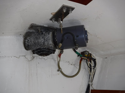
Windlass at installation in 2008 (Note jumper cable)


The project became an example of what happens when the tradesman will not listen to the customer and the customer is not assertive enough.
After repairing the broken connection bolt Mr X fitted the motor case upside down even though I insisted that was 180 degrees out.  He spun the case around several times and insisted that it would click into position only his way.  What saved the day was that the connection bolts were so close to the ceiling that he could not fit the nuts, forcing him to have a really close look and getting it right.
Mexico 2012 (Note black cable to top of windlass)

Then he insisted that the wiring sketch that I provided must be incorrect because there was no connection post at the top of the case.  The mention of "post" threw me off the scent and I relented because I could find no post at the top of the case and was puzzled because I NEVER make mistakes with basic sketches.  Mr X got the winch working after two short circuits resulting in major flashes and one half success where the winch was going, but backwards.  Oh, and he replaced the short jumper cable that had broken off at one of the connectors with a longer one that would reach the windlass case, never wondering how the original shorter cable could have spanned that distance.
My fundamental mistake was that I expected a marine electrician to know how to connect a windlass from experience.  This man acted as though he had never seen a windlass before. 

To avoid having to do some re-typing, here is a slightly edited version of the message that I sent to MR X:
Wiring by the Expert


Hello ,
You will recall that I had misgivings about the connection last Friday of the Orca VE2000 windlass on my boat Pachuca that you repaired.  Yes, I know that the windlass seemed to be working fine, but I was particularly concerned about the grounding cable from the motor to the gear housing, something that I knew was not as before.
I spent some time locating photos of the windlass to confirm that the diagram that I had sketched and presented to you was correct. 
Have a look the attached photos.
One photo shows the Orca at installation time in New Zealand in 2008.  The battery cables have not been connected, but you can clearly see the short jumper cable as sent from the factory.

Another photo shows the windlass in Mexico in 2012, which I took while painting the forward section of the boat.  You can  see the black battery negative cable passing to the top of the unit.
Wiring by the Owner

Also attached are photos of the cabling as you left it on Friday, to be compared with the photo as the cabling as I left it yesterday.
The mystery of the lack of post at the top of the motor case was simple to solve.  I felt along the top of the case and immediately felt a bolt hole. The bolt that you used to connect the black jumper cable to the windlass was in fact the bolt for connecting the black negative battery cable to the top of the motor case.
Why did the wiring work both ways?  I found the wiring diagram for the Orca VE2000 and working with a friend we concluded that the unit is capable of lowering as well as raising the anchor.  Mine is set up for raising only.  Because of the complex internal wiring it is possible to get the same result several connection paths.
Having said that, you'll understand why I prefer the connection as before.  It looks like the jumper cable connects F1 and F2 (F for "Field"), which are used for raising and lowering the anchor.  This was probably done because the windlass was shipped for "raise only" as the default.  The red positive battery cable is connected to "A" (for "Armature").  The black positive battery cable is connected to the top of the case.


Regards,
Robert


Reinstating the Anchor Windlass - Part 1

Pachuca has not a working electric anchor windlass since 6 Feb 2011 when Brenda and I were lucky to not lose the boat and swim for our lives in an electrical fire during the passage from Isla San Francisco and the fishing village of San Evaristo in the Sea or Cortez.  (see http://pachucaroundtheworld.blogspot.com.au/2011/02/fire-and-water.html)

I knew that basic cause of the electrical fire was the direct connection of the house bank of batteries to the windlass battery with two fairly light gauge wires and no fuse, diode, resistor, or any other protection measure in the circuit.  I vowed not to restore the windlass until I was confident that I was using a safe design.  The problem was how to somehow trickle charge the windlass battery from the House bank. In the subsequent six years I have raised anchor manually using a winch handle on top of the windlass.

Fortunately my brother Arnold is an electrical engineer, and he was able to send schematics of possible solutions.  However, it was not until face-to-face discussions with him during my recent visit to the USA that I felt confident enough of my understanding of the designs to actually do something.

The basic design is:


The design addresses the analysis that the fundamental problem is the amperage not during normal recharge, but whenever the anchor is being raised when the windlass battery is at low voltage, which passes the entire load of the windlass motor, an Orca VE2000 rated at 1500 watts, to the house bank.  Thus the key component is a relay which cuts off the connection between the two banks while the windlass is energized and the anchor is being raised and reestablishes it when the windlass is idle.

I started off by purchasing a new windlass battery.  I was first offered a lead-acid battery for about $300 but I'm done with lead-acid batteries on boats and insisted on an AGM or gel battery.  I purchased an Ultimate Xtreme” 110 a/h, 546 CCA AGM battery for $449.


At this point Stephen, Brenda's son, became interested and he provided invaluable help that complemented Arnold's ongoing assistance.

A fundamental question was the gauge of wire sufficient for connecting the House bank to the new windlass battery.  Arnold had calculated that the current along the wires would be well below 5 amps, so I settled on the thickest wire in the shop that would fit into a large crimp connector, which has an area of 4 mm sq giving a capacity of about 12 amps.

Then it was time to procure a relay, something that I knew nothing about.  Stephen pointed me to Jaycar where I purchased a 10-amp car relay.   I learned about the 5 pins on the relay from Youtube and most important, that I had to use pin 87A instead of 87 because I wanted the connection to be made by default and broken when the trigger activated the relay.

Stephen educated me on resistors where heat generation and dissipation was a big issue and we settled on a pair of .47 ohm resistors.

Then it was diode time and I purchased a 6 amp diode, the largest capacity available at Jaycar,

Stephen then salvaged a large heat sink from an amplifier that he was dismantling for part.  This went a long way to solving the heat dissipation problem and also provided a platform for the other components.
Heat Sink

Stephen also introduced me to a wonderful circuit simulator that allows him to define any circuit that he chooses them run it to see what happens.  We verified that the design would work and were able to explore the interaction between the strength of the resistors and current flow, particularly when the differential voltage is low.

At this point I have the system almost completed and ready for testing (gulp!).

15 amp in line fuse
 The heat sink "board" is tucked high at the end of the sail locker, protected from water and encroachment by sails and equipment stored in the space. The green electrical tape along the lower part of the board is to prevent short circuits.  Stephen thought that it was a good idea to put an in-line fuse at the beginning of the cable run.  It is a blade-type fuse inside of the small red plastic case along the wiring.

I have mounted the relay at the top right corner of the board.  When the relay is triggered the connection will be made and current will flow through the two resistors (white) and the diode (small, black and gray).  The idea of the diode is to prevent the charging of the main house bank by the windlass battery.
Heat Sink and Components

I wanted to use a 15-am breaker at the main switch panel, but the panel is full to capacity I deemed freeing up a breaker to be too difficult and dangerous.  (The rebuilding and extending the main panel is a project for the future.)

Instead I purchased a 15 amp breaker from Jaycar and mounted it by drilling a small hole in the electrical panel.  This style of breaker cannot be manually set and reset, but fortunately there was a free switch (Test Bat 1, Test Bat 2) that works so that I will have the capability of manually shutting down the entire circuit.

In parallel with this was the repair and installation of the windlass itself, which will be covered in another blog entry.


Blog Archive

Contributors

Statistics Click Me